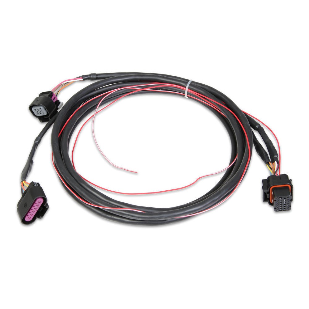
Find Lokar Drive-by-Wire Electronic Throttle Control Pedal Assemblies and get Free Shipping on Orders Over $99 at Summit Racing! Lokar drive-by-wire electronic throttle control pedal assemblies are the first programmable electronic throttle pedals for the automotive aftermarket. They feature a programmable, non-contact, solid-state Hall effect sensor for most GM, Ford, and Mopar applications. Gas Pedal Pad Replacement fits Many Compatible with Chevy GMC Repair Kit See Listing for Application Details GMC OEM NEW Accelerator Pedal Pad w/Position Sensor 07-11 Chevrolet 25832864 ACDelco 213-2820 GM Original Equipment Accelerator Pedal with Module. The function of the throttle control is operated by what we know as an accelerator or gas pedal. In earlier model vehicles, this pedal was connected to a cable that ran from the pedal to the engine and was connected to a mechanical linkage mounted to a carburetor or throttle body.
‘Fly-by-wire' systems are being used in a lot of cars and pickups on the road today and one of the most common ‘Fly-by-Wire' systems in use is the one that graces most of the newer GM pickups: the Electronic Throttle Body.
As you have probably already observed, there are 8 wires sticking out of the Electronic Throttle Body. When looking down at the Electronic Throttle Body's connector, the top row (from left to right) has 4 wires which are labeled from A to D (see photo). The second row (bottom row) from left to right, the wires are labeled E to H (see photo). General Motors introduced electronic throttle, or drive-by-wire, with the LS1 engine in the 1997 Corvette. Electronic throttle was released before cable throttle for the LS-series engine family. In 1998, the Camaro and Firebird received a cable throttle LS1 engine.
Gas Pedal For Sig P320

Everything you read about these systems indicate that they are the best thing to ever happen to automobiles. One of the statements that really makes me laugh is this one: 'The ETC delivers outstanding throttle response and greater reliability than a mechanical connection'.
The problems I've had with a throttle cable are so few and so far inbetween that I don't recall when was the last time I replaced one.. When was the last time you replaced a throttle cable?
OK, enough of my ranting, in this article, I'll focus on the circuits of the Electronic Throttle Body and how to perform some basic tests on it. You may also be interested in the following tutorials:

- P0120 TP Sensor 1 Circuit Malfunction (With Electronic Throttle Body).
- P0220 TP Sensor 2 Circuit Malfunction (With Electronic Throttle Body).
Puedes encontrar este tutorial en Español aquí: Lo Esencial del Cuerpo del Acelerador Electrónico (GM 5.3L, 6.0L) (en: autotecnico-online.com).
What Is Throttle By Wire
Circuit Descriptions Of The GM Electronic Throttle Body

‘Fly-by-wire' systems are being used in a lot of cars and pickups on the road today and one of the most common ‘Fly-by-Wire' systems in use is the one that graces most of the newer GM pickups: the Electronic Throttle Body.
As you have probably already observed, there are 8 wires sticking out of the Electronic Throttle Body. When looking down at the Electronic Throttle Body's connector, the top row (from left to right) has 4 wires which are labeled from A to D (see photo). The second row (bottom row) from left to right, the wires are labeled E to H (see photo). General Motors introduced electronic throttle, or drive-by-wire, with the LS1 engine in the 1997 Corvette. Electronic throttle was released before cable throttle for the LS-series engine family. In 1998, the Camaro and Firebird received a cable throttle LS1 engine.
Gas Pedal For Sig P320
Everything you read about these systems indicate that they are the best thing to ever happen to automobiles. One of the statements that really makes me laugh is this one: 'The ETC delivers outstanding throttle response and greater reliability than a mechanical connection'.
The problems I've had with a throttle cable are so few and so far inbetween that I don't recall when was the last time I replaced one.. When was the last time you replaced a throttle cable?
OK, enough of my ranting, in this article, I'll focus on the circuits of the Electronic Throttle Body and how to perform some basic tests on it. You may also be interested in the following tutorials:
- P0120 TP Sensor 1 Circuit Malfunction (With Electronic Throttle Body).
- P0220 TP Sensor 2 Circuit Malfunction (With Electronic Throttle Body).
Puedes encontrar este tutorial en Español aquí: Lo Esencial del Cuerpo del Acelerador Electrónico (GM 5.3L, 6.0L) (en: autotecnico-online.com).
What Is Throttle By Wire
Circuit Descriptions Of The GM Electronic Throttle Body
There are three major components of the GM Electronic Throttle Body and they are:
- Throttle body.
- Throttle Actuator Control (TAC) module.
- And Accelerator Pedal Assembly.
In this section, we'll focus on the Electronic Throttle Body. As you have probably already observed, there are 8 wires sticking out of the Electronic Throttle Body.
When looking down at the Electronic Throttle Body's connector, the top row (from left to right) has 4 wires which are labeled from A to D (see photo).
The second row (bottom row) from left to right, the wires are labeled E to H (see photo).
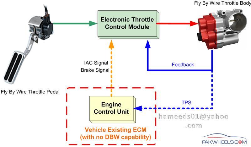
Fly By Wire Throttle Controller
and here are their specific descriptions:
- A: (Yellow wire) TAC Motor Control -1.
- B: (Black with White stripe wire) Low Reference.. Sensor Ground.
- C: (Brown wire) TAC Motor Control -2.
- D: (Black) Low Reference.. Sensor Ground.
- E: (Light Blue with Black wire) 5 Volt Reference.
- F: (Purple) TP Sensor 2 Signal.
- G: (Dark Green) TP Sensor 1 Signal.
- H: (Grey) 5 Volt Reference.
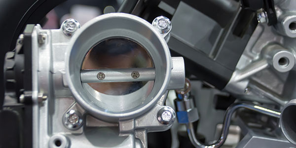
Fly By Wire Throttle Body
Spongebob squarepants episodes torrent download. Let's turn the page and find out how the throttle body works in this system..
